Now that we have covered the somewhat tricky route of tracing gear curves from images (which, by the way, you can use to create meshes out of any image) in part I, let’s have a look at the eMachineShop way. eMachineShop is a free gear designing software from the firm by the same name. They allow you to use their proprietary software for free in personal use, and then you can order the final product from them in a variety of machining finishes. I commend such an approach, especially since the software exports pure STL for our needs.
You can download the software package from eMachineShop.com and install it. When you start it the first time, you see a tutorial screen, but you can turn it off once you have the hang of the software. As it happens, it is very powerful, but a little quirky.
The main window looks like this:

It is a regular Windows program so you can find all the main elements in it very easily. When you select File – New, you see the extensive list of designs you can get out of it:

The fun part is, gears are just one of useful designs. For example, a 5 sided machined box with accompanying lid is available in any size you need, so if you know the size of your robotics project for example, you can design a box for it and print it. Once you have selected the design you want, and hit OK, the system will give you a 3D view into the design. Here, I chose the default bolt and hit OK, and this is what you see:

So, let’s take a real case. Suppose you want a gear that has 40 teeth and is close to 50 mm in diameter, and another one that matches it at 20 teeth, giving you a 4:2 ratio. You also want to have the bore in the center to be 10mm for easy design in the supporting structures department in Blender. First you get the default Spur gear up and it will look like that (File – New – Spur gear):
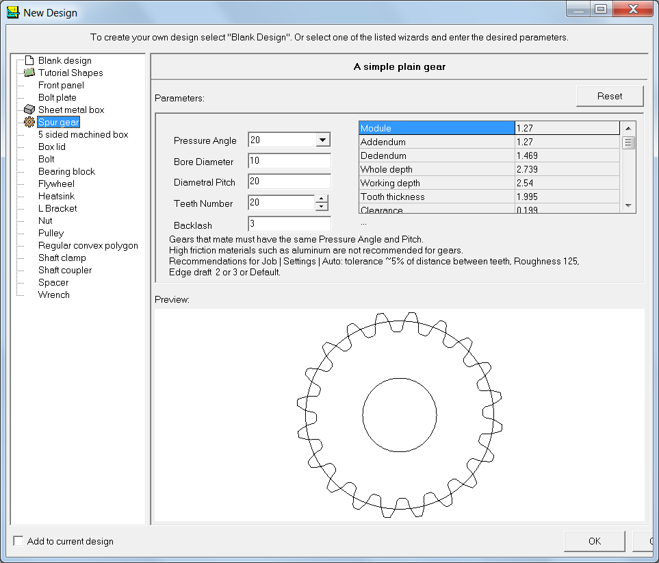
Note the Teeth number is now 20. Scroll down the properties list box on the top right to see Outside Diameter value, then change the number of teeth to 40. This will give you an outside diameter of 53mm, which is fine for now. I don’t change the Pressure Angle setting now, but if you want, you can adjust the gear Diametral Pitch. This governs the amount of teeth on an inch of the circumference of the gear. The higher the number here, the more teeth you will have, so if you change the default 20 to 21, you will have an outside diameter of 50.8mm. That’s close enough for me.
Then hit OK, and you will see your new gear in 3D Just drag with your mouse to rotate it in all directions:

And when you close the window, you will see the design with some additional info. Now you can add the second gear. Select File – New, select Spur Gear, keep the number of teeth at 20, change the Diametral Pitch to 21 to correspond to the other gear, and check the Add to Current Design. Before you hit OK, see the Outside Diameter: it is 26.61mm. With the Add to Current Design checked, the software shows both gears together:

All that remains is to export to STL. This is done in the regular way, via File – Export. Please note that both the gears will be one object in Blender, so if you want to separate them and reposition, you need to go into Edit mode in Blender and then select all vertices of one gear, and with the P command separate them into two meshes. This is the Import STL view in Blender:

Note that the grid is fully inside the bigger gear, so this has been imported in real size. Therefore you need not scale them when you export the final set-up for printing. But now let’s separate the gears and then design a platform with two axles on it. Go into Edit mode, make sure all vertices are visible, and select the larger gear. With all vertices selected, press P for Separate, and then select By selection. Now you will have a new mesh called 2gears.001 (or whatever your gear object was called before:

And now all that remains is to add a cube below the two gears, add two cylinders to function as axles, and attach the cylinders to the box. You can then align everything in a nice printable layout and export it all in one STL file, or, if you prefer more flexibility, export all three in separate files and add them onto the Repetier Host separately. In any case, you should get something like this:

Don’t make the axles by copying the hole circles, they will be too tight. Just size them so that you can see some slack around the axles in the hole, then print. I have been surprised by the accuracy of Minifactory – if you copy a hole into a cylinder, they are exactly the same size. Here’s a projected view of the objects:

If you tried to slice and print this, you would need to create support structures for the gears, and it would not be a good idea. Therefore, move the base and axles away from the gears before exporting. Remember to align them in the Z direction. I usually try to create a realistic print set before exporting.
As I said, you can select all three objects and then export, but this allows you less flexibility, for example in scaling the thickness of the gears (the base will also get scaled). The net result is the same in any case – you will wind up with the same slicing job regardless of the setup of the objects. For this example, I will export all three as one. There is no need to go via netFabb, because the gears are manifold straight from the eMachineShop, and the cylinders and cube have not been tampered with.

Slicing this will let you see how the object will build.


And finally a couple of pictures of a real life print. I am sorry that this is not the exact same print job as I have dealt with above, but it is close enough.


I hope this two part blog post has brought you ideas of how to prepare your own gears for any eventual project you may have. I would be interested to learn if you have tried the methods in these posts and whether you found this useful.
![]()