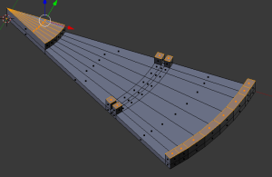
So far so good – we have the scanner base and the vertical arcs.
The turntable consists of 12 pieces of a circle, 30 degrees each, and with a 3mm thickness overall and a 6mm edge and center.

This design was the easiest to arrive at by taking a circle with 72 vertices, then deleting all but 7 of them. This shows the situation after selecting the 7 vertices, extruding out a little, then snapping the selected vertices to the center:

Now it’s a good idea to move into the top view and add a couple of edge loops. These will help forming the center for the axle cup, as well as the bolt walls and the thick edge. Here you see the first, which appears in the center of the piece as always and I have then moved it out to the edge just by eye. No need to be exact here.

You need all these edge lops when you extrude the piece out to form the parts.

The next issue is splitting the edges of the piece so you can raise the relevant parts later. To do this, the easiest way is to select the edges you need and split them like this – after you have selected the edges, merely click on Subdivide, and you will be left with these faces:

Now you can select the entire item and extrude up along the Z axis for 3 millimeters. For this it is best to be in a side view:

Now, select the parts you need raised for the edge as well as the bolt walls.

And extrude up again along the Z axis for 5 mm, except for the edge, which needs another 3 mm extruded. This is to allow for the axle cup, which is 3mm thick.

This is a print-ready item already, but while you’re here, it’s a good idea to note the size of the raised center part and create a round receptable for it, which I call the axle cup. Just create a circle of the same size as the cup. extrude out a couple millimeters, then up on the edge another 2 mm. The final part is shown on the top of this blog, and the full assembled turntable looks like this:

The next part will handle the assembly and installation of the webcam, as well as the software for it.
![]()