In the previous post I showed how to build a single digit display using one 7 segment LED unit. That’s nice but not very useful as such, since single digits can only show limited amounts of data. To go further, you can either add digits and chain them together, as will be seen in Part 3 of this project, or, you can use a four segment LED unit and one shift register.
This time we will use a four segment LED to produce a countdown clock. You will see that this setup is very versatile and you can easily modify it to show the current time, for example, or temperature as in 23°C or 77°F, with the third digit providing the degree character and the last digit the temperature scale.
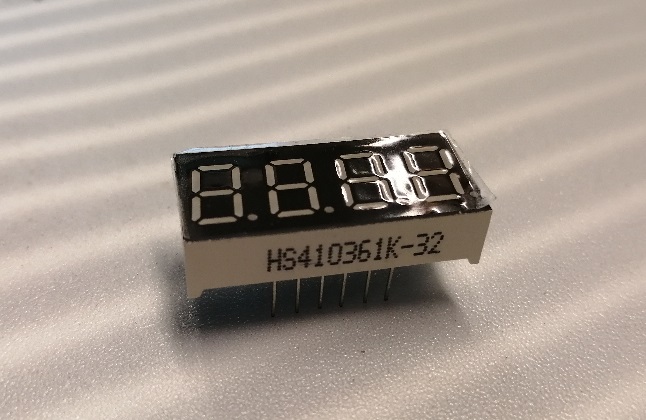
This is the most common four digit, seven segment LED unit. It has 12 pins, not ten like the one digit thing. That’s because it has been wired so that every digit has its own anode, and the remaining 8 pins correspond to the segments.
The four segment LED works due to the persistence of vision. Not every digit is on all the time, but rather, the four digits are refreshed at 5 millisecond intervals, ie. 200 times per second, that the eye can’t discern them as individually lit. For this, you need to send Arduino four bytes of data via a shift register as before, to be displayed in quick succession.
Parts and connections
So, your parts list is the same as before with a breadboard, a 74HC595 shift register, a bunch of male-male jumper wires, and a display as shown above. My application for this little device is a countdown timer, and the code includes a method for taking a value in seconds, then finding out the minutes and seconds, further dividing them into tens of minutes, minutes, tens of seconds and seconds. These four, single digit, values are sent to the shift register as four consecutive bytes. This is the pins list:
| PIN NUMBER | PIN NAME | GOES TO | |
| 74HC595 | 1 | Q1 | LED 5 |
| 74HC595 | 2 | Q2 | LED 10 |
| 74HC595 | 3 | Q3 | LED 1 |
| 74HC595 | 4 | Q4 | LED 2 |
| 74HC595 | 5 | Q5 | LED 4 |
| 74HC595 | 6 | Q6 | LED 7 |
| 74HC595 | 7 | Q7 | LED 11 |
| 74HC595 | 8 | GND | GND |
| 74HC595 | 9 | DATA OUT | NEXT SHIFT REGISTER |
| 74HC595 | 10 | MR | 5V |
| 74HC595 | 11 | SH_CP | ARD Clock Pin |
| 74HC595 | 12 | ST_CP | ARD Latch Pin |
| 74HC595 | 13 | OE | GND |
| 74HC595 | 14 | DS | ARD Data Pin |
| 74HC595 | 15 | Q0 | LED 3 |
| 74HC595 | 16 | VCC | 5V |
The connections on the 74HC595 are as before, with the difference that you need to supply all four anodes with their own power. This is achieved by connecting the anodes on the LED unit as follows:
| PIN NUMBER | GOES TO | ||
| LED PIN | 1 | SHIFT Q3 | |
| LED PIN | 2 | SHIFT Q4 | |
| LED PIN | 3 | SHIFT Q0 | |
| LED PIN | 4 | SHIFT Q5 | |
| LED PIN | 5 | SHIFT Q1 | |
| LED PIN | 6 | ARD 4 | Anode pin |
| LED PIN | 7 | SHIFT Q6 | |
| LED PIN | 8 | ARD 5 | Anode pin |
| LED PIN | 9 | ARD 6 | Anode pin |
| LED PIN | 10 | SHIFT Q2 | |
| LED PIN | 11 | SHIFT Q7 | |
| LED PIN | 12 | ARD 7 | Anode pin |
Logic and coding
Your application may vary, but the essential thing is to be able to separate each digit into its own byte, so 27 isn’t 27, but a 2 and a 7. When I made the countdown timer, I did some Excel first to find out the digits in every moment (45 minutes is 2700 seconds):
| sec | mins | secs | splitmins1 | splitmins2 | splitsecs1 | splitsecs2 |
| 2700 | 45 | 0 | 4 | 5 | 0 | 0 |
Mins is derived from int(seconds/60), which drops the remainder.
Secs is the modulo 60 division of Minutes, which gives just the remainder.
| sec | mins | secs | splitmins1 | splitmins2 | splitsecs1 | splitsecs2 |
| 2700 | 45 | 0 | 4 | 5 | 0 | 0 |
| 2699 | 44 | 59 | 4 | 4 | 5 | 9 |
| 2698 | 44 | 58 | 4 | 4 | 5 | 8 |
| 2697 | 44 | 57 | 4 | 4 | 5 | 7 |
| 2696 | 44 | 56 | 4 | 4 | 5 | 6 |
| 2695 | 44 | 55 | 4 | 4 | 5 | 5 |
| 2694 | 44 | 54 | 4 | 4 | 5 | 4 |
etc.
Splitmins 1 and 2 are again an integer division of minutes, and modulo division of minutes. Splitsecs are the same for seconds. After I got this working in Excel, I did the same thing for Arduino:
int second = 2700;          // Define variable for starting time in seconds
int mins= 0;                // variable for holding minutes
int secs = 0;               // variable for holding seconds
int splitmins1 = 0;         // variable for holding first digits of minutes
int splitmins2 = 0;         // variable for holding second digits of minutes
int splitsecs1 = 0;         // variable for holding first digits of seconds
int splitsecs2 = 0;         // variable for holding second digits of seconds
byte myArray[] = {0x99, 0x92, 0xc0, 0xc0}; // an array holding the four digits
initially with the numbers 4,5,0,0 in it
There is also a second array that holds the bytes that form the numbers and letters:
byte num[] = {0xc0, 0xf9, 0xa4, 0xb0, 0x99, 0x92, 0x82, 0xf8, 0x80, 0x90, 0x88, 0x83, 0xc6, 0xa1, 0x86, 0x8e};
These are the values of 0 through F in hexadecimal notation. So, if you want to send the values 1 2 3 4 to the display, you place 0xf9, 0xa4, 0xb0, and 0x99 in myArray. You remember the picking of values from the previous post, where it is handled in more detail.
This is the actual maths:
second--;                     // second minus 1
if (second==0) {              // handling the time out issue
  second = 2700;
}
mins = int(second/60);        // minutes as 45, 44, 43...
secs = int(second % 60);      // seconds of every minute
splitmins1 = int(mins / 10);  // first digit of minutes
splitmins2 = int(mins % 10);  // second digit of minutes
splitsecs1 = int(secs / 10);  // first digit of seconds
splitsecs2 = int(secs % 10);  // second digit of seconds
myArray[0] = num[splitmins1]; // get first digit hexcode from num array
myArray[1] = num[splitmins2]; // get second digit hexcode from num array
myArray[2] = num[splitsecs1]; // get third digit hexcode from num array
myArray[3] = num[splitsecs2]; // get fourth digit hexcode from num array
After this it’s just the issue of sending this out to the shift register, then having it deal out the four digits in quick succcession. The code below is again based on Freenove’s excellent tutorials, but has been edited to do more than just show 0123.
#include <FlexiTimer2.h>  // Contains FlexiTimer2 Library
int latchPin = 5; //12;          // Pin connected to ST_CP of 74HC595(Pin12)
int clockPin = 6;//13;          // Pin connected to SH_CP of 74HC595(Pin11)
int dataPin = 7; //11;           // Pin connected to DS of 74HC595(Pin14)
int comPin[] = {13, 12, 11, 10};  //{7, 6, 5, 4};// Common pin (anode) of 4 digit 7-segment display
int doorPin = 3;            // pin for monitoring room door being closed
int second = 2700;          // Define variable for starting time in seconds
int mins= 0;                // variable for holding minutes
int secs = 0;               // variable for holding seconds
int splitmins1 = 0;         // variable for holding first digits of minutes
int splitmins2 = 0;         // variable for holding second digits of minutes
int splitsecs1 = 0;         // variable for holding first digits of seconds
int splitsecs2 = 0;         // variable for holding second digits of seconds

// Define the encoding of characters 0-F for the common-anode 7-Segment Display
byte num[] = {0xc0, 0xf9, 0xa4, 0xb0, 0x99, 0x92, 0x82, 0xf8, 0x80, 0x90, 0x88, 0x83, 0xc6, 0xa1, 0x86, 0x8e};
byte myArray[] = {0x99, 0x92, 0xc0, 0xc0}; //array for representing led characters, inititally 4500
void setup() {
  // set pins to output
  pinMode(latchPin, OUTPUT);
  pinMode(clockPin, OUTPUT);
  pinMode(dataPin, OUTPUT);
  //pinMode(doorPin, INPUT);
  for (int i = 0; i < 4; i++) {
    pinMode(comPin[i], OUTPUT);
  }
  digitalWrite(doorPin, HIGH);       // set door lock monitor pin to high
  FlexiTimer2::set(1000, timerInt);  // configure the timer and interrupt function
  FlexiTimer2::start();              // start timer
}

void loop() {
  showArray();
}

void showArray(){
  for (int i = 0; i < 4; i++) {
    // Select a single 7-segment display
    chooseCommon(i);
    // Send data to 74HC595
    writeData(myArray[i]);
    delay(5);
    // Clear the display content
    writeData(0xff);
  }
}

// the timer interrupt function of FlexiTimer2 is executed every 1s

void timerInt() {
  //if(digitalRead(doorPin)==LOW){  // while the switch at pin 3 is closed, this will run
    second--;                     // second minus 1
    if (second==0) {              // handling the time out issue
      second = 2700;
    }
    mins = int(second/60);        // minutes as 45, 44, 43…
    secs = int(second % 60);      // seconds of every minute
    splitmins1 = int(mins / 10);  // first digit of minutes
    splitmins2 = int(mins % 10);  // second digit of minutes
    splitsecs1 = int(secs / 10);  // first digit of seconds
    splitsecs2 = int(secs % 10);  // second digit of seconds
    myArray[0] = num[splitmins1]; // get first digit hexcode from num array
    myArray[1] = num[splitmins2]; // get second digit hexcode from num array
    myArray[2] = num[splitsecs1]; // get third digit hexcode from num array
    myArray[3] = num[splitsecs2]; // get fourth digit hexcode from num array
  //}
  //else {                          // switch opens, the clock shows the time left at opening
  //  delay(10);
  //}

}

void chooseCommon(byte com) {
  // Close all single 7-segment display
  for (int i = 0; i < 4; i++) {
    digitalWrite(comPin[i], LOW);
  }
  // Open the selected single 7-segment display
  digitalWrite(comPin[com], HIGH);
}

void writeData(int value) {
  // Make latchPin output low level
  digitalWrite(latchPin, LOW);
  // Send serial data to 74HC595
  shiftOut(dataPin, clockPin, LSBFIRST, value);
  // Make latchPin output high level, then 74HC595 will update the data to parallel output
  digitalWrite(latchPin, HIGH);
}
This works when you have just one 4 digit, 7 segment LED. If you want to use more such units, you can connect the shift registers to eah other via the data output of the first register wired to the data input of the next. This will hopefully be covered in the fourth episode of this three-part blog on LEDs, but first I will show you how to convert this small scale countdown timer to a big digit timer. The elements I got are 4″, 10cm tall, red ones, and it looks rather impressive. They also have to be fed 12V, which is not manageable via 74HC595, but instead you need a chip called TPIC6B595 which can handle the voltage.
Final product
But just to show you how this project turned out, here’s a little video of it in operation.
![]()